sales06@switek.biz

+86 186 5927 5869

Shopping

Subscrib to Us
sales06@switek.biz
+86 186 5927 5869
Shopping
Subscrib to Us
Keywords:IML Robot; IML Robot Operating; In Mold Labeling Robotics
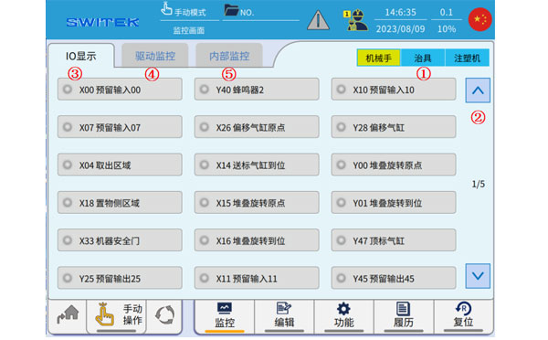
The "Monitor" which we're discussing here is where you'll have a clear understanding of the working stituation of the robotic arm. In monitor page you can check the signal of the robotic arm, the EOAT, the injection molding machine and the working status of the servo motor and the control system of the IML robot for a fast diagnose of the broken point of the system.
Click  icon, the following page pops up the monitoring page:
| No | Name | Function |
|---|---|---|
| (1) | Robot/Jig/IMM | IO displays the category, click to quickly switch to the corresponding signal page. |
| (2) | Page | Click to switch to the I/O page |
| (3) | IO display | Real-time ON/OFF display of all current input and output points. |
| (4) | Drive monitoring | Real-tme display of speed, torque, load rate, and deviation of each axis servo motor. |
| (5) | Internal monitoring | Real-time display of internal I/O status. |
Use (1) or (2) to switch the IO display, and the front light is on to indicate that the signal is on.
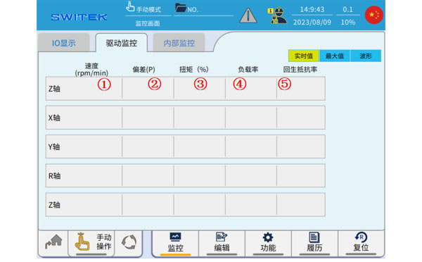
3.5.2 Drive monitoring
Real-time values
| No | Name | Function |
|---|---|---|
| (1) | Speed (rpm/min) | Real-time display of the running speed of each axis. |
| (2) | Deviation (P) | Real-time display of deviations in each axis. |
| (3) | Torque (%) | Real-time percentage display of torque for each axis. The instantangeous torque of the servo motor can reach up to 300% of the rated torque. |
| (4) | Load factor | Real-time display of the operating load factor of each axis. (100% max) |
| (5) | Resilience resistance rate | Real-time display of the load rate of respawn resistance. |
Maximum

| No | Name | Function |
|---|---|---|
| (1) | Forward Maximum Speed | A record of the maximum speed of each axis as it moves in the positive direction. |
| (2) | Negative maximum speed | A record of the maximum speed of each axis moving in a negative direction. |
| (3) | Positive maximum deviation | Records the maximum deviation of each axis in the positive direction. |
| (4) | Negative maximum deviation | A record of the maximum deviation of each axis in the negative direction. |
| (5) | Forward maximum torque | A record of the maximum torque of each axis as it moves in the positive direction. |
| (6) | Negative maximum torque | A record of the maximum toruqe of each axis when it moves in the negative direction. |
| (7) | Reset | The maximum value previously recorded is cleared. |
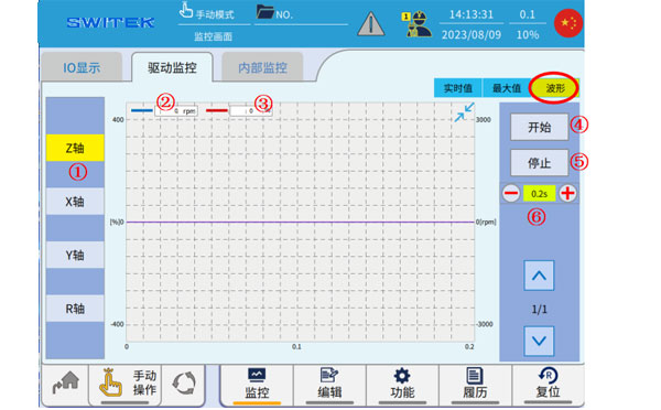
Waveform
| No. | Name | Function |
|---|---|---|
| (1) | Axis selection | Click to select the axis to display. |
| (2) | Torque (%) | The blue waveform curve shows the change in torque. The instantaneous torque of the servo motor can reach up to 300% of the rated torque. |
| (3) | Speed(rpm/min) | The red waveform curve shows the change in velocity. |
| (4) | Start | After selecting the (1) axis, click "Start" to start the waveform sampling. |
| (5) | Stop | Stop waveform sampling |
| (6) | The waveform displays the scale. | Click "+" and "-" to zoom in and out of the displayed waveform. |
3.5.3 Internal Monitor
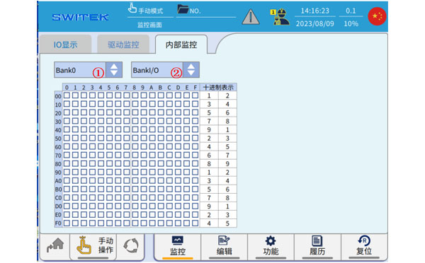
"Internal monitoring" refers to the monitoring of the ON/OFF of the internal flag position of the controller, which is divided into 5 blank *2 units, a total of 10 areas, and the switching between bank and unit is completed through (1) and (2).


Contact SWITEK IML
sales06@switek.biz
+86 186 5927 5869

DongGuan, GuangDong, China
HuangYanZheng©Copy Right