sales06@switek.biz

+86 186 5927 5869

Shopping

Subscrib to Us
sales06@switek.biz
+86 186 5927 5869
Shopping
Subscrib to Us
Keywords:Panasonic A6 Servo Motor, Panasonic A6 Servo Motor Driver, Panasonic A6 Servo Motor setting instruction
The Panasonic A6 series of AC servo moto provided the protocol to communicate with the other facilities via USB, RS232 and RS485 etc. In this chapter we're discuss how to connect the Panasonic A6 series of AC servo motor to the communication connector.
This is used for USB connection to a personal computer. It is possible to change the parameter setting and perform monitoring.
| Application | Symbol | Connector Pin No. | Contents |
|---|---|---|---|
| USB signal terminal | VBUS | 1 | Use for communication with personal computer. |
| D- | 2 | ||
| D+ | 3 | ||
| — | 4 | Do not connect. | |
| GND | 5 | Connected to group of control circuit. |
Caution → Use commercially available USB mini-B connector for the driver.

This is used for connection to the host controller when two or more units are used. RS232 andd RS485 interfaces are supplied.
| Application | Symbol | Connector Pin No. | Contents |
|---|---|---|---|
| Signal ground | GND | 1 | Connected to ground of control circuit. |
| NC | — | 2 | Do not connect |
| RS232 signal | TXD | 3 | RS232 The transmission / reception method. |
| RXD | 4 | ||
| RS485 signal | 485- | 5 | RS485 The transmission/reception method. |
| 485+ | 6 | ||
| 485- | 7 | ||
| 485+ | 8 | ||
| Frame ground | FG | Shell | Connected with protective earth terminal in the servo driver. |
Connector (plug): 1-2201855-1 or 2040008-1 (optional, available from Tyco Electronics) [Connector pin assignment] 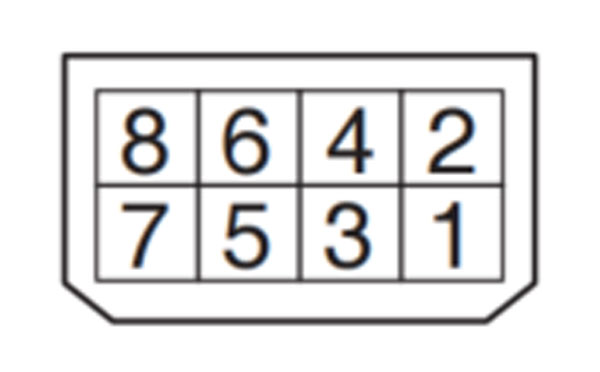 (Viewed from cable)
• This servo driver features 2 kinds of communication function, RS232 and RS485, and you can use in 3 connecting methods.
Remarks → • X1 to X6 are used for the secondary circuit. To connect these terminals to the primary power supply (particularly, the 24 VDC power supply for brake), insulation is required. Do not connect these terminals to the same power supply.
Related page → •P.7-130 "Connector Kit for Communication Cable (for RS485, RS232)"
Connect the host (PC or controller) to an driver through RS232
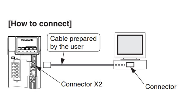
Shut off both power of the PC and the driver before inserting/pulling out of the connector.
By connecting the host (PC and host controller) and one driver via RS232 and connecting other drivers via RS485 each other, you can connect multiple drivers.
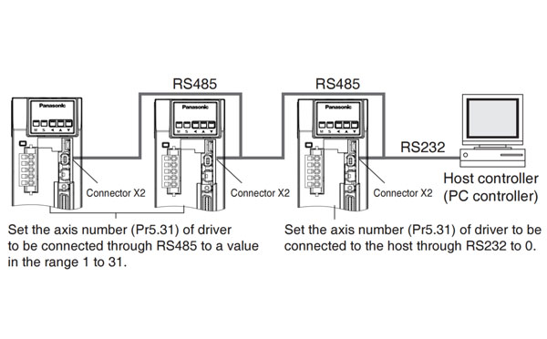
Note → • You can connect up to 32 drivers with the host. • For details, refer to P.7-28, "Communication" of Supplement.
Communications between the host (PC or controller) and multiple drivers can be made through RS485.
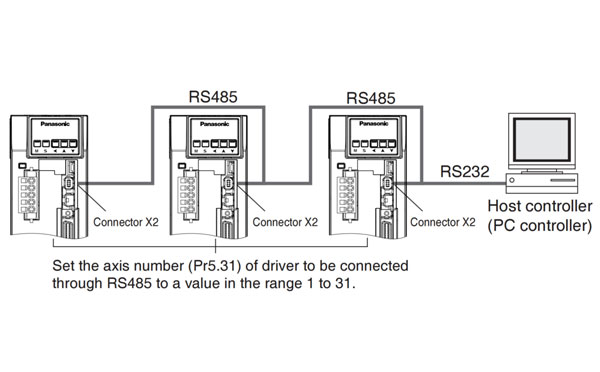
Note → • You can connect up to 31 drivers with the host. • For details, refer to P.7-28 "Communication" of Supplement.
A safety by-pass plug is supplied as standard equipment. Do not disconnect it in normal times.
When controlling the safety function from the connected host controller, accessory connector cannot be used. Prepare and wire the connector (option) as specified below.
Since the standard connector cannot be used when controlling the safety function from the host controller, purchase the optional connector and make connection as shown below. When you do not configuring a safety circuit, please use the safety bypass plug of accessory to the driver.
For wiring of the safety bypass plug supplied with the driver, refer to the figure below.
| Application | Symbol | Connector Pin No. | Contents |
|---|---|---|---|
| NC | — | 1 | Do not connect. |
| — | 2 | ||
| Safety input 1 | SF1- | 3 | These are two independent circuits that turn off the operation signal to the power module to shut off the motor current. |
| SF1+ | 4 | ||
| Safety input 2 | SF2- | 5 | |
| SF2+ | 6 | ||
| EDM output | EDM- | 7 | This is an output for monitoring the failure of the safety function. |
| EDM+ | 8 | ||
| Frame ground | FG | Shell | Connected with protective earth terminal in the servo driver. |
Connector (plug): 2201855-1 or 2013595-1 (optional, available from Tyco Electronics) [Connector pin assignment]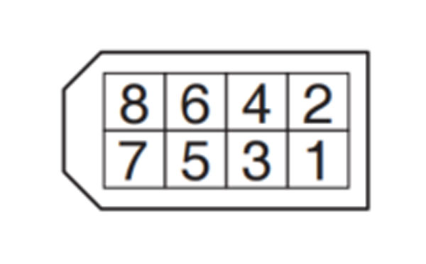 (Viewed from cable)
Safety bypass plug supplied with the driver (internal wiring)
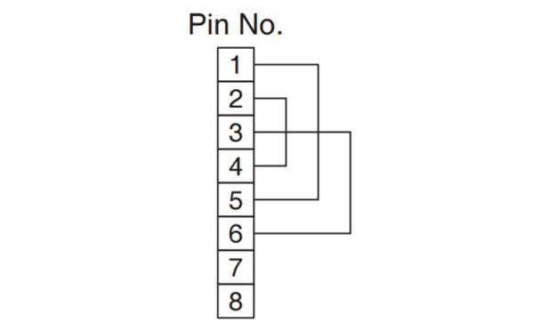
Wiring if the safety circuit is not configured. When using the safety function, do not make these connections.
Remarks → • X1 to X6 are used for the secondary circuit. To connect these terminals to the primary power supply (particularly, the 24 VDC power supply for brake), insulation is required. Do not connect these terminals to the same power supply.
Caution → • Disconnecting this connector during operation results in immediate stop.
Related page → • P.7-130 "Connector Kit for Safety"
Relaed page → • For details, refer to P.3-31, "Wiring Diagram to the connector, X4" and P.3-33, "Inputs and outputs on connector X4".
•Specifications of the Connector, X4
| Connector to be prepared by customer | Manufacturer | |
|---|---|---|
| Part name | Part No. | |
| Connector (soldering type) | DF02P050F22A1 | Japan Aviation Electronics Ind. |
| Connector cover | DF02P050B22A1 | |
| or | ||
| Connector (soldering type) | 54306-5019 | Molex Inc. |
| Connector cover | 54331-0501 | |
| or | ||
| Connector (soldering type) | 10150-3000PE | Sumitomo 3M |
| Connector cover | 10350-52A0-008 | |
or equivalent
Note → • For details, refer to P.7-108, "Options" of Supplement.
Remarks → • Tightening torque of the screws for connector (X4) for the connection to the host be 0.3 N*m. Larger tightening torque than these may damage the connector at the driver side.
Provide a power supply for the external scale on your part or use the following power output (250 mA or less).
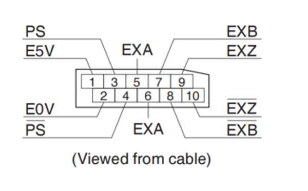
| Application | Symbol | Connector Pin No. | Contents |
|---|---|---|---|
| Power supply output | EX5V | 1 | Supply the power of external scale or A, B, Z phase encoder. |
| EX0V | 2 | Connected to ground of control circuit. | |
| I/F of external scale signals | EXPS | 3 | Serial signal The transmission / reception method. |
| /EXPS | 4 | ||
| A, B, Z phase Endoder signal input | EXA | 5 | Parallel signal reception Correspondence speed: 4 Mpps (after quardruple) |
| /EXA | 6 | ||
| EXB | 7 | ||
| /EXB | 8 | ||
| EXZ | 9 | ||
| /EXZ | 10 | ||
| Frame ground | FG | Shell | Connected with protective earth terminal in the servo driver. |
Connector (plug) sirial external signal: MUF-PK10K-X (by J.S.T. Mfg. Co., Ltd.)
• Caution
If you set up the external scale ratio to smaller value than 50/position loop gain (Pr1.00 and Pr.1.05), you may not be able to control 1 pulse unit, even if within the range as described above. Setup of larger scale ratio may result in larger noise.
Remarks → • X1 to X6 are used for the secondary circuit. To connect these terminals to the primary power supply (particularly, the 24 VDC power supply for brake), insulation is required. Do not connect these terminals to the same power supply.
Related page → • P.4-6 "Details of Parameter" • P.7-131 "Connector Kit for External Scale"
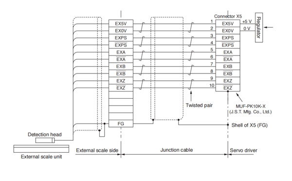
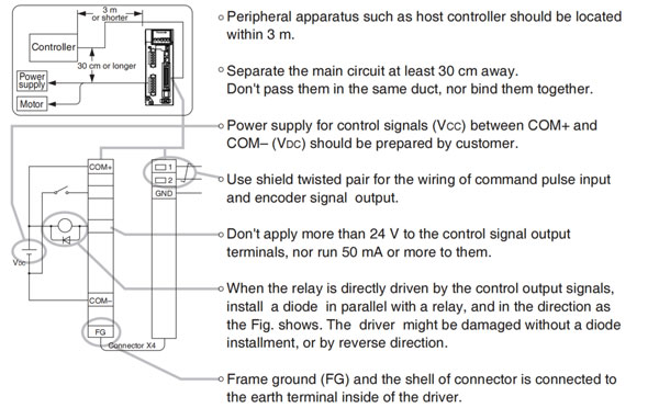
Wire the signals from the external scale to the external scale connector, X5.
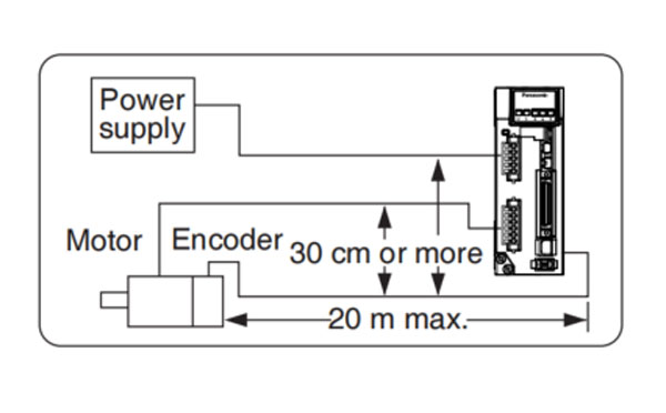
 ) as much as possible (30 cm or more). Do not pass these wires in the same duct, nor bundle together.
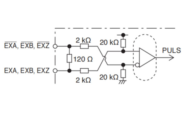
 • EXA, EXB, EXZ input circuit
Remarks → • X1 to X6 are used for the secondary circuit. To connect these terminals to the primary power supply (particularly, the 24 VDC power supply for brake), insulation is required. Do not connect these terminals to the same power supply.
Remarks → • X1 to X6 are used for the secondary circuit. To connect these terminals to the primary power supply (particularly, the 24 VDC power supply for brake), insulation is required. Do not connect these terminals to the same power supply.
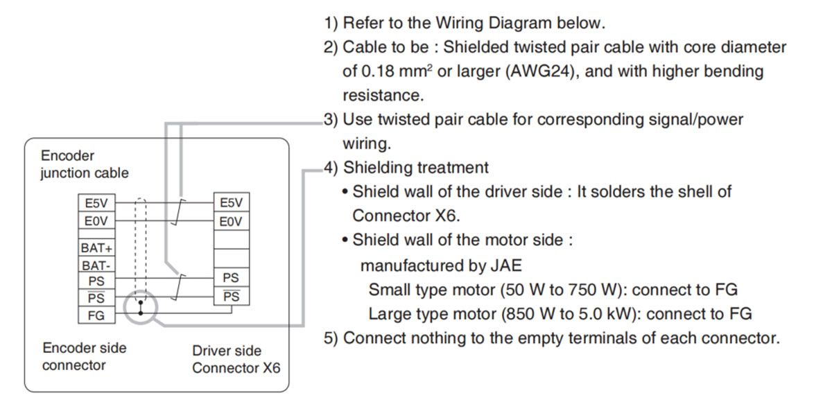
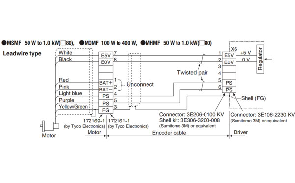
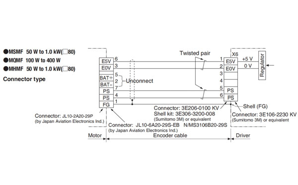
Related page → • P.7-131 "Connector Kit for Encoder"
• In case of 23-bit absolute encoder (as multi-turn data was be used)
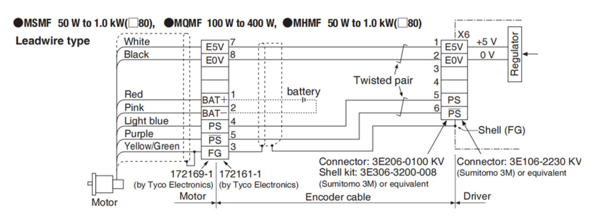
Remarks → • Connect the battery for absolute encoder across 1P and 2P of the junction connector (the figure above).
• A battery holder and a battery connection cable should be the option cable or prepared by the user.
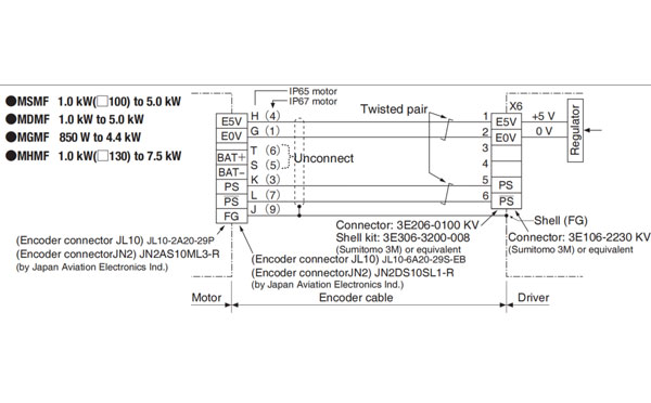
Caution → • Tighten the motor connector mounting screw (M2) with a torque between 0.19 and 0.21 N*m. To avoid damage, be sure to use only the screw supplied with the connector.
• Do not remove the gasket supplied with the junction cable connector. Securely install the gasket in place. Otherwise, the degree of protection of IP67 will not be guaranteed.
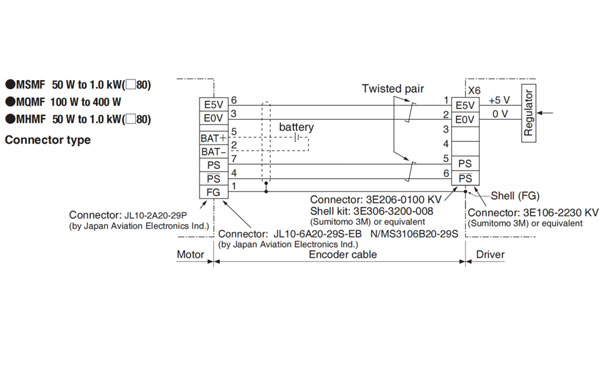
Remarks → • Connect the battery for absolute encoder across 5P and 2P of the junction connector (the figure above).
• A battery holder and a battery connection cable should be option cable or prepared by the user.
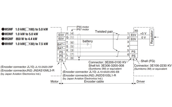
Remarks → • Connect the battery for absolute encoder across 6P and 5P of the junction connector (the figure above).
• A battery holder and a battery connection cable should be the option cable or prepared by the user.
• In case of 23-bit absolute encoder (as single turn data was be used)
Caution → • Tighten the motor connector mounting screw (M2) with a torque between 0.19 and 0.21 N*m. To avoid damage, be sure to use only the screw supplied with the connector.
• Do not remove the gasket supplied with the junction cable connector. Securely install the gasket in place. Otherwise, the degree of protection of IP67 will not be guaranteed.
Remarks → • X1 to X6 are used for the secondary circuit. To connect these terminals to the primary power supply ( particularly, the 24 VDC power supply for brake), insulation is required. Do not connect these terminals to the same power supply.


Contact SWITEK IML
sales06@switek.biz
+86 186 5927 5869

DongGuan, GuangDong, China
HuangYanZheng©Copy Right