sales06@switek.biz

+86 186 5927 5869

Shopping

Subscrib to Us
sales06@switek.biz
+86 186 5927 5869
Shopping
Subscrib to Us
Keywords:Panasonic A6 Servo Motor, Panasonic A6 Servo Motor Driver, Panasonic A6 Servo Motor setting instruction
It's important to have a correct connector to have the Panasonic A6 series of motor properly wired. Here in this chapter we'll discuss how to select the correct connectors for different motors in different wiring conditions.
• When the motors of <MSMF, MQMF, MHMF> are used, they are connected as shown belwo.
Connector: Made by Tyco Electronics k.k, (The figures below show connectors for the motor)
| 3 | 2 | 1 |
| 6 | 5 | 4 |
| 9 | 8 | 7 |
172169-1
*When use absolute encoder (multi-turn data is not used). do not connecdt to 1-pin and 2-pin.
| PIN NO. | Application |
|---|---|
| 1* | BAT+ |
| 2* | BAT- |
| 3 | FG (SHIELD) |
| 4 | PS |
| 5 | PS |
| 6 | NC |
| 7 | E5V |
| 8 | E0V |
| 9 | NC |
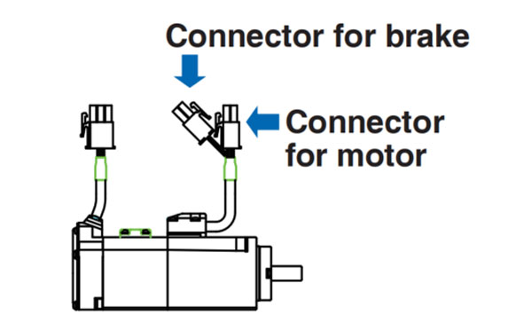
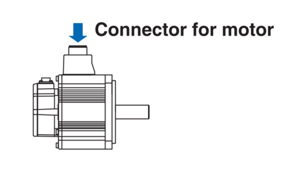
Connecor for motor
| 2 | 1 |
| 4 | 3 |
172167-1
| PIN No. | Application |
|---|---|
| 1 | U-phase |
| 2 | V-phase |
| 3 | W-phase |
| 4 | Ground |
Connector for brake
| 1 |
| 2 |
172165-1
| PIN No. | Application |
|---|---|
| 1 | Break |
| 2 | Breake |
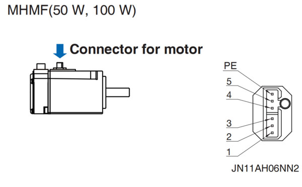
• When the motors of <MSMF, MQMF, MHMF (50W to 1.0kW)> are used, they are connected as shown below.
Connector:Made by Japan Aviation Electronics Industry, Ltd. (The figures below show connectors for the motor.)
*Do not remove the gasker supplied with the junction cable connector. Securelly install the gasket in place. Otherwise, the degree of protection of IP67 will not be guaranteed.
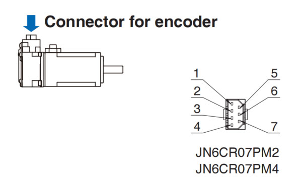
| PIN No. | Application |
|---|---|
| 1 | FG(SHIELD) |
| 2* | BAT- |
| 3 | E0V |
| 4 | PS |
| 5* | BAT+ |
| 6 | E5V |
| 7 | PS |
*When use absolute encoder (multi-turn data is not used), do not connect to 2-pin and 5-pin.
Tightening torque of the screw (M2) 0.19 N-m to 0.21 N-m
*Be sure to use ony the screw supplied with the connector, to avoid damage.
MSMF(50W to 1.0kW(☐80))
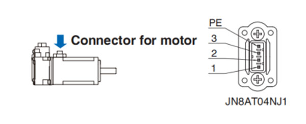
| PIN No. | Application |
|---|---|
| 1 | U-phase |
| 2 | V-phase |
| 3 | W-phase |
| PE | Ground |
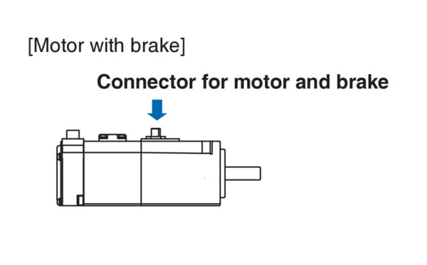
Tightening torque of the screw (M2) 0.085 N-m to 0.095 N-m (screwed to plastic)
*Be sure to use only the screw supplied with the connector, to avoid damage.
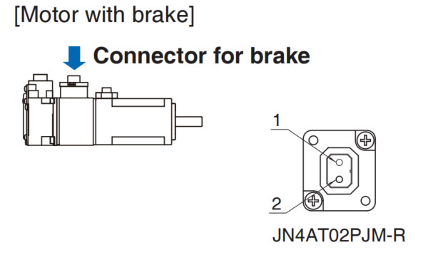
| PIN No. | Application |
|---|---|
| 1 | Break |
| 2 | Break |
*Electromagnetic break is a nonpolar device. Tightening torque of the screw (M2) 0.19 N-m to 0.21 N-m
*Be sure to use only the screw supplied with the connector, to avoid damage.
Remarks → Do not connect anything to NC.
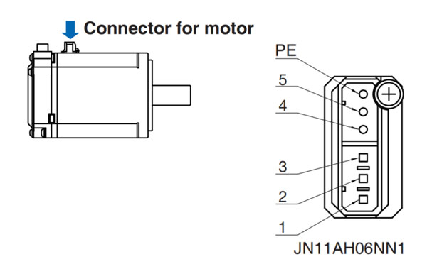
| PIN No. | Application |
|---|---|
| 1 | U-phase |
| 2 | V-phase |
| 3 | W-phase |
| 4 | NC |
| 5 | NC |
| PE | Ground |
Tightening torque of the screw (M2) 0.085 N-m to 0.095 N-m (screwed to plastic)
*Be sure to use only the screw supplied with the connector, to avoid damage.
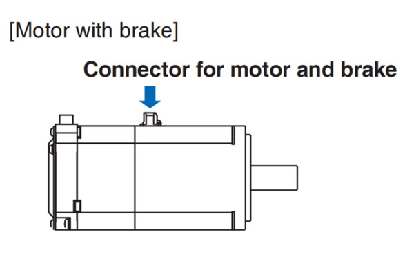
| PIN No. | Application |
|---|---|
| 1 | U-phase |
| 2 | V-phase |
| 3 | W-phase |
| 4 | NC |
| 5 | NC |
| PE | Ground |
*Electromagnetic brake is a nonpolar device.
| PIN No. | Application |
|---|---|
| 1 | U-phase |
| 2 | V-phase |
| 3 | W-phase |
| 4 | NC |
| 5 | NC |
| PE | Ground |
Tightening torque of the screw (M2) 0.085 N-m to 0.095 N-m (screwed to plastic)
*Be sure to use only the screw supplied with the connector, to avoid damage.
| PIN No. | Application |
|---|---|
| 1 | U-phase |
| 2 | V-phase |
| 3 | W-phase |
| 4 | NC |
| 5 | NC |
| PE | Ground |
*Electromagnetic brake is a nonpolar device.
Remarks → Do not connect anything to NC.
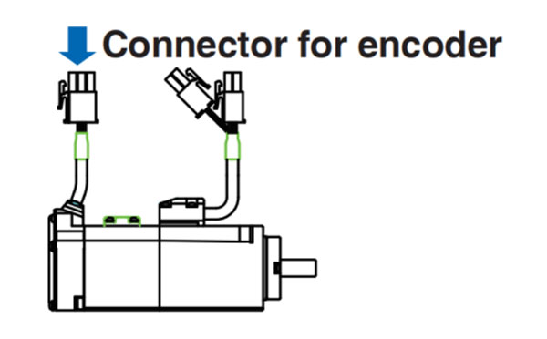
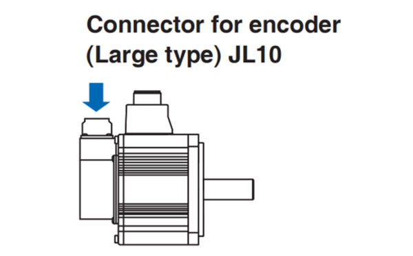
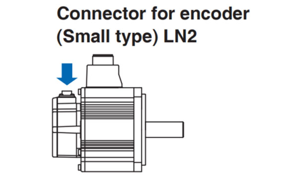
•When the motors of <MSME(1.0kW(☐100) to 5.0kW), MDMF, MGMF, MHMF(1.0kW(☐130) to 5.0kW)> are used, they are connected as shown below.
Connector: Made by Japan Aviation Electronics Industry, Ltd. (The figures below show connectors for the motor.)
• Connector for encoder
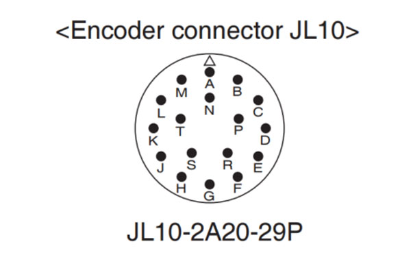
| PIN No. | Application |
|---|---|
| A | NC |
| B | NC |
| C | NC |
| D | NC |
| E | NC |
| F | NC |
| G | E0V |
| H | E5V |
| J | FG(SHIELD) |
| K | PS |
| L | PS |
| M | NC |
| N | NC |
| P | NC |
| R | NC |
| S* | BAT- |
| T* | BAT+ |
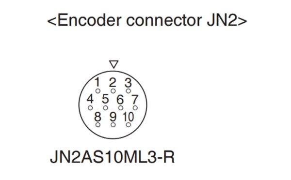
| PIN No. | Application |
|---|---|
| 1 | E0V |
| 2 | NC |
| 3 | PS |
| 4 | E5V |
| 5* | BAT- |
| 6* | BAT+ |
| 7 | PS |
| 8 | NC |
| 9 | FG(SHIELD) |
| 10 | NC |
*When use absolut encoder (multi-turn data is not used), do not connect to 5-pin andd 6-pin.
*When use absolut encoder (multi-turn data is not used), do not connecdt to S-pin and T-pin.
Table of Connector for motor and Connector for brake
| Motor model | Motor capacity | 200V | |
|---|---|---|---|
| with Brake | without Brake | ||
| MSMF | 1.0kW(☐100) to 2.0kW | A | C |
| 3.0kW to 5.0kW | B | D | |
| MDMF | 1.0 kW to 2.0kW | A | C |
| 3.0kW to 5.0kW | B | D | |
| Motor model | Motor capacity | 200 V | |
|---|---|---|---|
| with Brake | without Brake | ||
| MGMF | 850 W to 1.8 kW | A | C |
| 2.9 kW, 4.4 kW | B | D | |
| MHMF | 1.0 kW(☐130) to 1.5 kW | A | C |
| 2.0 kW to 5.0 kW | B | D | |
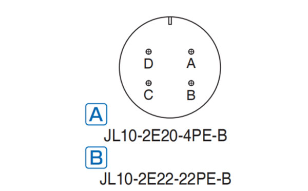
| PIN No. | Application |
|---|---|
| A | U-phase |
| B | V-phase |
| C | W-phase |
| D | Ground |
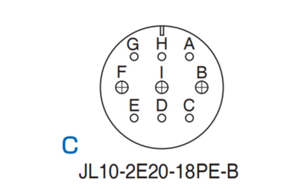
| PIN No. | Application |
|---|---|
| G | with Brake: Brake |
| without Brake: NC | |
| H | with Brake: Brake |
| without Brake: NC | |
| A | NC |
| F | U-phase |
| I | V-phase |
| B | W-phase |
| E | Ground |
| D | Ground |
| C | NC |
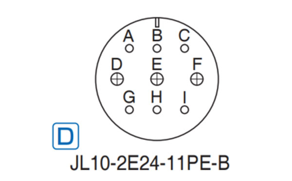
| PIN No. | Application |
|---|---|
| A | with Brake: Brake |
| without Brake: NC | |
| B | with Brake: Brake |
| without Brake: NC | |
| C | NC |
| D | U-phase |
| E | V-phase |
| F | W-phase |
| G | Ground |
| H | Ground |
| I | NC |
Remarks → Do not connect anything to NC.
•Follow the procedures below for the wiring connection to the Connector XA, XB, XC, and XD.
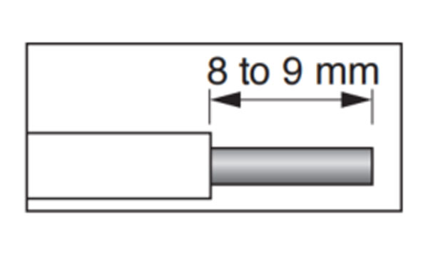
1.Peel off the insulation cover of the cable.
2.Insert the cable to the connector in the following 2 methods.
| (a) Using handle lever | (b) Using screw driver |
|---|---|
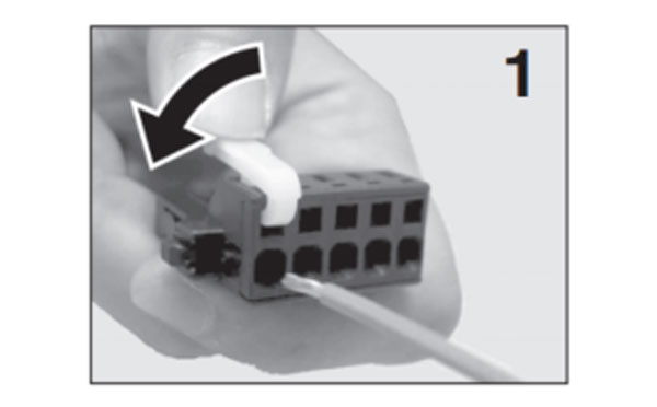 Attach the handle lever to the handling slot on the upper portion. Press down the lever to push down the spring. 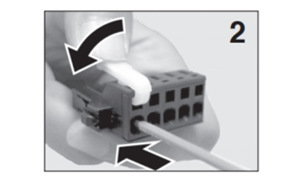 Insert the peeled cable while pressing down the lever, until it hits the insertion slot (round hole). 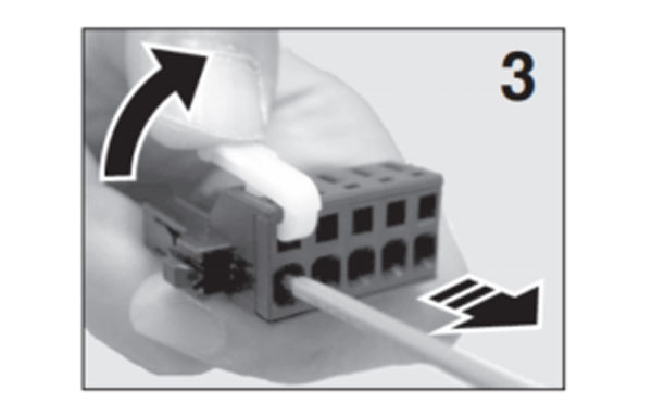 Release the lever. | 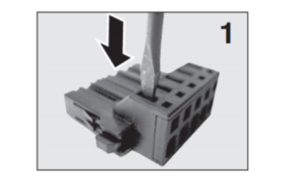 Press the screw driver to the handling slot on the upper portion to push down the spring. 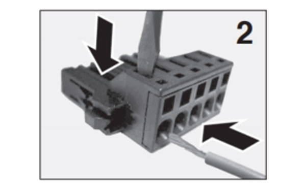 Insert the peeled cable while pressing down the screw driver, until it hits the insertion slot (round hole). 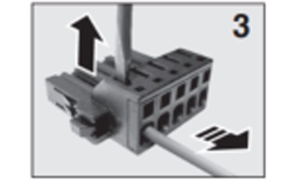 Released the screw driver. |


Contact SWITEK IML
sales06@switek.biz
+86 186 5927 5869

DongGuan, GuangDong, China
HuangYanZheng©Copy Right