sales06@switek.biz

+86 186 5927 5869

Shopping

Subscrib to Us
sales06@switek.biz
+86 186 5927 5869
Shopping
Subscrib to Us
Keywords:Panasonic A6 Servo Installation Instruction, Panasonic A6 Driver, Panasonic A6 Series Servo Motor Manual
You can control the speed according to the analog speed command from the host controller or the speed command set in the servo driver.
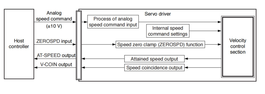
The analog speed command input voltage is converted to equivalent digital speed command. You can set the filter to eliminate noise or adjust the offset.
• Relevant parameters
| Parameter | Title | Range | Unit | Function |
|---|---|---|---|---|
| Pr3.00 | Speed setup, Internal/External switching | 0 to 3 | — | This driver is equipped with internal speed setup function so that you can control the speed with contact inputs only. |
| Pr3.01 | Speed command rotational direction selection | 0 to 1 | &mdash | Select the Positive/Negative direction specifying method. |
| Pr3.02 | Input gain of speed command | 10 to 2000 | (r/min)/V | Based on the voltage applied to the analog speed command (SPR), set up the conversion gain to motor command speed. |
| Pr3.03 | Reversal of speed command input | 0 to 1 | — | Specify the polarity of the voltage applied to the analog speed command (SPR). |
| Pr4.22 | Analog input 1 (Al1) offset setup | -5578 to 5578 | 0.359 mV | Set up the offset correction value applied to the voltage fed to the analog input 1. |
| Pr4.23 | Analog input 1 (Al1) filter | 0 to 6400 | 0.01 ms | Set up the time constant of 1st delay filter that the determinese the lag time behind the voltage applied to the analog input 1. |
Only for standard type and communication type are not provided with analog input.
You can control the speed by using the internal speed command set to the parameter. By using the internal speed command selections 1, 2, 3 (INTSPD 1, 2, 3), you can select best appropriate one among up to 8 internal speed command settings. Default setting uses the analog speed command. To use the internal speed command, select it through Pr3.00 "Internal/external speed setup".
• Relevant parameters
| Parameter No. | Title | Range | Unit | Function |
|---|---|---|---|---|
| Pr3.00 | Speed setup, Internal/External switching | 0 to 3 | — | This driver is equipped with internal speed setup function so that you can control the speed with contact inputs only. |
| Pr3.01 | Speed command rotational direction selection | 0 to 1 | — | Select the Positive/Negative direction specifying method. |
| Pr3.04 | 1st speed of speed setup | -20000 to 20000 | r/min | Set up internal command speeds, 1st to 1st. |
| Pr3.05 | 2nd speed of speed setup | Set up internal command speeds, 1st to 2nd. | ||
| Pr3.06 | 3rd speed of speed setup | Set up internal command speeds, 1st to 3rd. | ||
| Pr3.07 | 4th speed of speed setup | Set up internal command speeds, 1st to 4th. | ||
| Pr3.08 | 5th speed of speed setup | Set up internal command speeds, 1st to 5th. | ||
| Pr3.09 | 6th speed of speed setup | Set up internal command speeds, 1st to 6th. | ||
| Pr3.10 | 7th speed of speed setup | Set up internal command speeds, 1st to 7th. | ||
| 3.11 | 8th speed of speed setup | Set up internal command speeds, 1st to 8th. |
You can forcibly set the speed command to 0 by using the speed zero clamp input.
| Parameter No. | Title | Range | Unit | Function |
|---|---|---|---|---|
| Pr3.15 | Speed zero-clamp function selection | 0 to 3 | — | You can set up the function of the speed zero clamp input. |
| Pr3.16 | Speed zero clamp level | 10 to 20000 | r/min | Select the timing at which the position control is activated as the Pr3.15 Speed zero-clamp function selection is set to 2. |
The signal AT-SPEED is output as the motor reaches the speed set to Pr4.36 "Attained speed".
• Relevant parameters
| Parameter No. | Title | Range | Unit | Function |
|---|---|---|---|---|
| Pr4.36 | At-speed (Speed arrival) | 10 to 20000 | r/min | Set the detection timing of the speed arrival output (AT-SPEED). |
This signal is output when the motor speed is equal to the speed specified by the speed command. The motor speed is judged to be coincident with the specified speed when the difference from the speed command before/after acceleration/deceleration is within the range specified by Pr4.35 "Speed coincident range".
• Relevant parameters
| Parameter No. | Title | Range | Unit | Function |
|---|---|---|---|---|
| Pr4.35 | Speed coincidence range | 10 to 20000 | rmin | Set the speed coincidence (V-COIN) output detection timing. |
This function controls the speed by adding acceleration or decceleration instruction in the driver to the input speed command.
Using this function, you can use the soft start when inputting stepwise speed command or when using internal speed setup. You can also use S shaped acceleration/deceleration function to minimize shock due to change in speed.
• Relevant parameters
| Parameter No. | Title | Range | Unit | Function |
|---|---|---|---|---|
| Pr3.12 | Acceleration time setup | 0 to 10000 | ms/(1000 r/min) | Set up acceleration processing time in response to the speed command input. |
| Pr3.13 | Deceleration time setup | 0 to 10000 | ms/(1000 r/min) | |
| Pr3.14 | Sigmoid acceleration/deceleration time setup | 0 to 1000 | ms | Set S-curve time for acceleration/deceleration process when the speed command is applied. |


Contact SWITEK IML
sales06@switek.biz
+86 186 5927 5869

DongGuan, GuangDong, China
HuangYanZheng©Copy Right