sales06@switek.biz

+86 186 5927 5869

Shopping

Subscrib to Us
sales06@switek.biz
+86 186 5927 5869
Shopping
Subscrib to Us

With the control system developed by the Austria automatic company SIGMATEK GmbH & Co KG, SWITEK high speed side entry IML robot is providing a more efficient and outstanding performance for your quality bulk production of the IML Yogurt Cups.
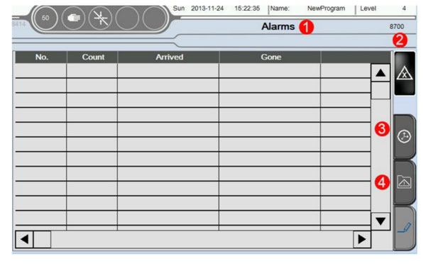
4.1 Alarms
Click Alarms button. As shown in the below picture of 1.6.1:
| No | Alarm | Illumination | Treatment |
|---|---|---|---|
| A004 to A015 | Axis Interior Min Limit | Indicates current actual limit is less than the set Min limit. | In the manual page, remove this axis to Min Limited Funcction/Servo Setup/Axis/**/Axis Assignment->Max Limited in program, actual limited must be more than this set value, suggestion for -1.00mm. |
| A021 to A032 | Axis interior Max limit | Indicates current actual limit more than the set Max limit | In the manual page, remove this axis to Max Limited Function/Servo Setup/Axis/**/Axis Assignment->Max Limited in program, actual limited must be less than this set value. This value is depended on the Mechanical Dimensions. |
| A041 to A052 | Axis position limit | Indicates axis' motion can not follow the speed of CNC instruction | -Function/Servo Setup/Axis/**/Axis Control Assignment-> Max limited deviation, the first value is set 10mm more than the second. The second show the current actual deviation, suggested to adjust driver's rigidity to decrease deviation. -Function/Servo Setup/Axis Assignment/**/Axis Control Assignment -> advance the value of KV, VU, suggested to advance 50 each time -adjust accelerated speed, Function/Servo Setup/Axis configuration |
| A061 to A072 | Axis Alarms | Indicates breakdown happens inthe current axis** | -Axis control module (CST 022/CNC 305/CNC 115 and so on) has not been tested -+24V/+5V power supply of Axis control module is abnormal -Check the corresponding limiting point configuration of I/O |
| A081 to A092 | Axis position Min limit | Indiccates that there is signal inputting in the Minimum limit sensor of current axis | -mechanical hand is located in the position beyond limit Check machine -misdescription happens in the transducer. Check transducer -Check the corresponding limiting point configuration of I/O |
| A101 to A112 | Axis position Max limit | Indicates that there is signal inputting in the Maximum limit sensor of currrent axis. | -mechanical hand is located in the position beyond limit. Check machine -misdescription happens in the transducer. Check ransducer -Check the corresponding point configuration of I/O |
| A121 | Emergency stop button Pressed down | Emergency stop of machine active on the Control panel. | -Rotate the Emergency stop of machine chockwise to loosen it/System Setup. function is , so this Emergency will not appear until Reboot; if check . Emergency disiappear automatically. -If Button Stop of hand controller virtual key is pressed down, reset this virtual key. |
| A122 | Pressure abnormal | pressure abnormal | Check pressure. Check wether or not pressure test has been turned on. |
| A123 | Emergency stop of machine active | Checked Emergency stop of machine put down |
|
| A124 | Safety equipment is abnormal | Machine safety door open |
|
| A125 | Quantity accomplished | Set quantity has been finished | Function/produce setup page->Quantity Setup |
| A126 | Reject part reaches setting limit | Amount of reject part has reached the number of set alarms | function/produce setup page - > Reject Alarm Interval |
| A127 | Cycle time overtime | Cyclical time exceeds the safety time scope. | function/produce setup page -> motion monitor time; 0 do not means monitor. |
| A128 | Fixture abnormal | Fixture motion beyond the set time of monitor |
|
| A129 | Module Open/Close signal abnormal | Conflict between Module Open and Module Close |
|
| A130 | Vacuum abnormal | Monitor of Vacuum exceed the set monitor time. |
|
| A131 | Division by zero error | Set parameter has been divided by 0. | Check whether set parameter has been divided by 0. Set parameter is too small. |
| A133 | Module Open Interval Time | Interval is too short between two Module Open |
|
| A141 to A149 | Baseboard slot modulel error | The order error in the second module Baseboard …… the order error in the ninth module Baseboard |
|
| A150 | CIV512 module error | Order of CIV 512 module tests wrong. |
|
| A151 A152 | Driver module | Order of Driver SDD/MDD tests wrong. Driver 1: PLC varan bus connects with the driver firstly; Driver 2: bus connects with this driver secondly |
|
| A161 | Module Open pattern Interval abnormal | Interval between the two Module Open Receive signal is too short |
|
| A162 | The label paper shortage | System receives the signal of label paper shortage |
|
| A163 | VBC error | The order of VBC module is tested wrong |
|
| A171 to A203 | Motion overtime | Automatic running, the motion time of corresponding axis exceeds safety time. |
|


Contact SWITEK IML
sales06@switek.biz
+86 186 5927 5869

DongGuan, GuangDong, China
HuangYanZheng©Copy Right