HIGH SPEED IML ROBOT
Keywords:Panasonic A6 Servo Motor, Panasonic A6 Servo Motor Driver, Panasonic A6 Servo Motor setting instruction
Introduction of Panasonic A6 Series Motor & Driver -- 2.1.2 Composition of Peripheral Equipments
Abstract
Conformance to international standards, the Panasonic A6 series of AC servo motor and driver must be composited with peripheral equipments in different environment. Here in this chapter we're discussing the wiring of the Panasonic A6 servo motor and driver with conformance to different international standards.
Installation Environment
Use the servo driver in the environment of Pollution Degree 1 or 2 prescribed in IEC-60664-1 (e.g. Install the driver in control panel with IP54 protection structure.)
-
Mandatory requirements to conform to EMC directive
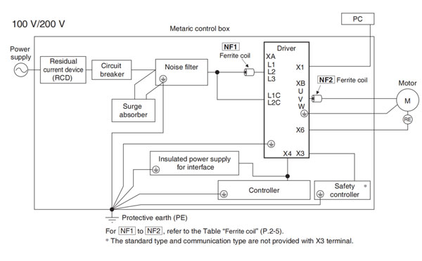
- Install the servo driver on the metallic casing (control board).
- Install noise filter and lightning surge absorber in the power supply line.
- Use braided shield cable (tin plated annealed copper wire) for I/O signal cable and encoder cable.
- Provide the noise filter, as shown in the figure, for each cable, I'O line and power source line to be connected to the servo driver.
- Shield of cables not shown on the figure should be directly grounded through PE. Because these conditions for EMC directive are affected by status of connected device, wiring, connection and location, compliance should be checked after completing installation.
Ferrite coil
| Symbol *1 | Cable Name | Amp. frame symbol | Option part No. | Manufacturer's part No. | Manufacturer | Qty. |
|---|---|---|---|---|---|---|
| NF1 | Power Cable | (100V)C (200V)C, D | DV0P1460 | ZCAT3035-1330 | TDK Corp. | 0 |
| (100 V)A, B (200 V)A, B, E | 1 | |||||
| NF2 | Motor cable | (100 V)A, B, C (200 V)A, B, C, C, E | 1 | |||
| (200 V)F | 2 |
*1 For symbols, refer to the Block Diagram "Installation Environment" (P. 2-4).
*2 The number of turns are 0.
Remarks → To connect the noise filter to the connector XB connection cable, adjust the sheath length at the tip of the cable, as required.
Caution → Fix the ferrite coil in order to prevent excessive stress to the cables.
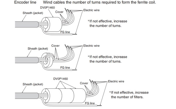
<Attaching ferrite coil>
Single wire -- Wind cables the number of turns required to form the ferrite coil.
Power wire -- If sheathed (jacketed): remove the sheath (jacket) to the length so that wires (L1, L2, L3) can be wound on the ferrite coil (including power line dedicated filter). For effective noise reduction capability, L1, L2 and L3 should be wound together. If not effective, increase the number of signal noise filters (including power line dedicated filters). (See figure below.)
Motor line -- When installing the ferrite coil (including motor line dedicated filter) to our optional cable, remove the sheath (jacket) to the length so that wires can be wound on the ferrite coil (including power line dedicated filter). For effective noise reduction capability, U, V and W should be wound together. If not effective, increase the number of ferrite coils (including power line dedicated filters). (See figure below.)
Encoder line -- Wind cables the number of turns required to form the ferrite coil.
Caution → Use options correctly after reading Operating Instructionsof the options to better undersstand the precautions. Take care not to apply excessive stress to each optional part.
Power Supply
| 100V type: (A to C-frame) | Single phase, 100V +10%/-15% to 120V +10%/-15% 50Hz/60Hz |
| 200V type: (A to D-frame) | Single/3-phase, 200V +10%/-15% to 240V +10%/-15% 50Hz/60Hz |
| 200V type: (E to F-frame) | 3-phase, 200V +10%/-15% to 240V +10%/-15% 50Hz/60Hz |
- This product is designed to be used in over-voltage category (installation category) III of EN61800-5-1:2007.
- Use an insulated power supply of DC12 to 24V which has CE marking or complies with EN60950.
Remarks →
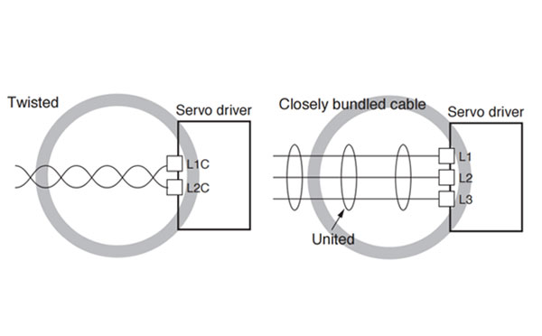
- Use sheathed (jacketed) cable, twisted cable or closely bundled cable for power cable.
- Power cable and signal wires must be sufficiently isolated from each other.
Circuit Breaker
Install a circuit breaker which complies with IEC standard Standards and UL recognized (Listed and  marked) between power supply and noise filter.
The short-circuit protection circuit on the product is not for protection of branch circuit.
The branch circuit should be protected in accordance with NEC and the applicable local regulations in your area.
Noise Filter
| Optional part No. | Voltage specifications for driver | Manufacturer's part No. | Applicable driver (frame) | Manufacturer |
|---|---|---|---|---|
| DV0P4170 | Single phase 100 V/200 V | SUP-EK5-ER-6 | A, B-frame | Okaya Electric Ind. |
| DV0PM20042 | 3-phase 200 V | 3SUP-HU10-ER-6 | A, B-frame | |
| Single phase 100 V/200V 3-phase 200 V | C-frame | |||
| DV0P4220 | Single/3-phase 200 V | 3SUP-HU30-ER-6 | D-frame | |
| DV0PM20043 | 3-phase 200 V | 3SUP-HU50-ER-6 | E-frame | |
| DV0P3410 | 3-phase 200 V | 3SUP-HL50-ER-6B | F-frame |
Remark →
- Select a noise filter whose capacity is commensurate with the power source capacity (in consideration of the load codnition).
- For the detailed specifications of each noise filter, contact the manufacturere.
- When two or more servo drivers are used with a single noise filter at the common power source, consult with the noise filter manufacturer.
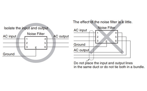
- Do not run the input and output wiring on the same passage: noise resistance with drop. (Figure at lower right)
- Isolate the input and output line from each other. (Figure at lower left)
Surge Absorber
| Option part No. | Voltage specifications for driver | Manufacturer's part No. | Manufacturer |
|---|---|---|---|
| DV0P1450 | 3-phase 200 V | R.A.V-781BXZ-4 | Okaya Electric Ind. |
| DV0P4190 | Single phase 100 V/200 V | R.A.V-781BWZ-4 |
Remarks → When performing without voltage test of machine and equipment, be sure to remove the surge absorber; otherwise, it will be damaged.
Residual current device
Install a residual current device (RCD) at primary side of the power supply.
Select a RCD of type. B prescribed in IEC60947-2, JISC8201-2-2
Grounding
- To prevent electric shock, be sure to connect the ground terminal (
 ) of the driver, and the ground terminal (PE) of the control panel.
 - The ground terminal () must not be shared with other equipment. Two ground terminals are provided.
Structure of Control Board
If there is a gap at cable inlet/outlet, mounting hole of operation panel or a door, radio waves will penetrate into or radiate out through the gap. To prevent unfavorable conditions due to radio frequency activities, observe the following control board design and selection instruction.
- The control board should be made of metal which provides electrical continuity.
- The control board should not have electrically-isolated conductor.
- All units installed in the casing should be grounded to the case.
Increasing Noise Resistance of Control I/O Signal
When noise is applied to the control input/output, it causes displacement andd malfunctioning of I/O signal.
- X1 to X6 are secondary side circuit which should be isolated from the primary power source (24 VDC control power source, 24 VDC braking power source and 24 VDC for regenerative resistor). Do not connect the secondary side circuit to primary power source and ground wire. Otherwise, I/O signal will cause error operation.
- Control power source should be completely isiolated from external operating power source. Newver connect the ground of the control power source to that of external power source.
- The signal line should have shield, the both end of which should be connected to the ground.
Note → For driver and applicable peripheral equipments, refer to P.2-10 "Driver and List of Applicable Peripheral Equipments". Cuation → Use options correctly after reading Operating Instructions of the options to better understand the precautions. Take care not to apply excessive stress to each optional part.