HIGH SPEED IML ROBOT
Keywords:Panasonic A6 Servo Installation Instruction, Panasonic A6 Driver, Panasonic A6 Series Servo Motor Manual
Panasonic A6 Motor & Driver Instruction 3.4 Inputs and outputs on connector X4 — Interface Circuit (Output)
Abstract
Here in this chapter is the wiring instruction of input/out connecting to the contacts of switches and relays, or open collector output transistors.
Output Circuit
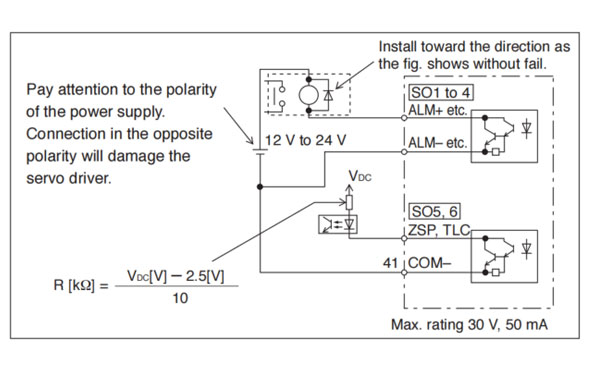
- The output circuit is composed of open collector transistor outputs in the Darlington connection, and connect to relays or photocouplers.
- There exists collector to emitter voltage, VCE(SAT) of approx, 1V at transistor-ON, due to the Darlington connection of output or. Note that normal TTL IC cannot be directly connected since it does not meet VIL.
- There are two types of output, one (2 systems of SO5, SO6) which emitter side of the output transistor is independent and is connectable individually, and the one (4 systems of SI1 to SI4) which is common to - side of the control power supply (COM-).
- If a recommended primary cutrent value of the photocoupler is 10 mA, decide the resistor valu using the formula of the below figure.
- When accepting the output signal through a logic circuit, e.g. gate, influence from noises should be prevented.
For the recommended primary current value, refer to the data sheet of the equipment and photocoupler to be used.
• For function, refer to P.3-48 to P.3-52. P.3-55
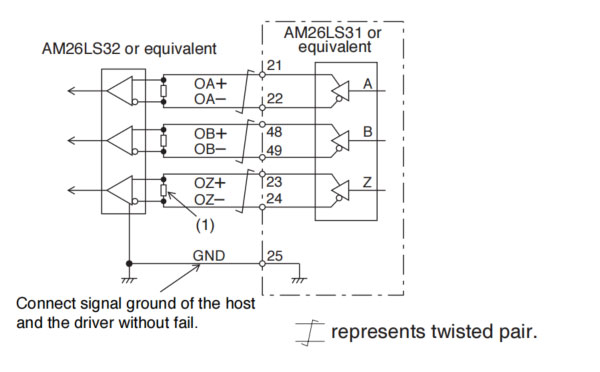
- Feeds out the divided encoder outputs (A,B and Z-phase) in differential through each line driver.
- At the host side, receive these in line receiver. Install a terminal resistor (approx. 330 Ω)(right figure (1)) between line receiver inputs without fail.
- These outputs are not insulated.
- For function, refer to P.3-51.
- Feedsf out the Z-phase signal among the encoder signals in open collector. This output is not insulated.
- Receive this output with high-speed photocouplers at the host side, since the pulse width of the Z-phase signal is narrow.
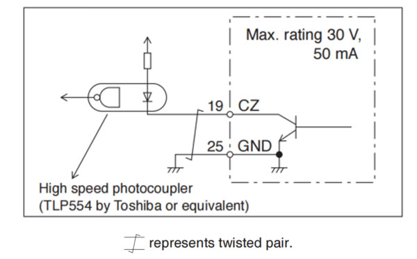
- For function, refer to P.3-51.
- There are two outputs, the speed monitor signal output (SP) and the torque monitor signal output (IM).
- Output signal width is ±10 V.
- The output impedance is 1 kΩ. Pay an atteention to the input impedance of the measuring instrument or the external circuit to be connected.
<Resolution> (1)Speed monitor output (SP)
With a setup of 6 V/3000 r/min, the resolution converted to speed is 4 r/min/8 mV.
(2) Torque monitor output (IM)
With a relation of 2 V/rated torque (100%), the resolution converted to torque is 0.4%/8 mV.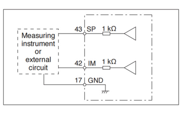
- For function, refer to P.3-52.